
Introduction: The Architecture of a Industrial Investment
Building a commercial fertilizer production line—whether it is a high-capacity organic compost plant, a steam-granulated NPK line, or a high-precision specialty fertilizer blending facility—is a complex, capital-intensive engineering journey. A common mistake among new investors is viewing the project simply as “buying a bundle of machines.” In reality, a successful plant requires a synchronized, multi-disciplinary engineering approach.
If you miss a step in material balancing, your dryers will underperform. If your site layout ignores forklift clearance and raw material zoning, your operational costs (OPEX) will skyrocket.
To help you navigate this complex lifecycle, this comprehensive guide breaks down the commercial fertilizer plant construction process into 11 critical engineering steps, moving systematically from the initial feasibility phase to the final commercial trial run.
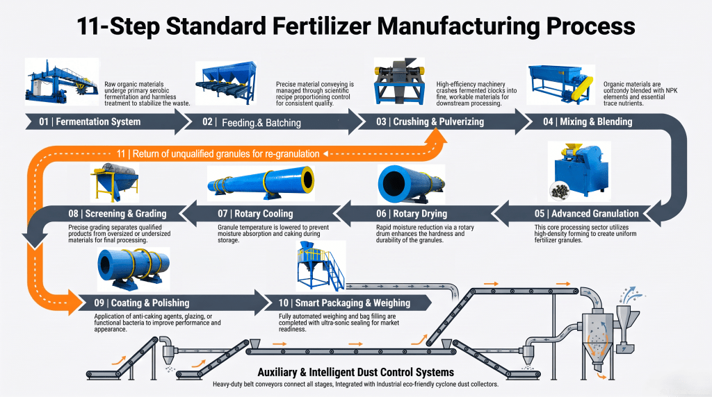
Phase 1: Pre-Construction & Engineering Design (Steps 1–4)
Step 1: Feasibility Study & Raw Material Analysis
Before a single piece of steel is forged, the project’s technical and financial viability must be strictly validated. This step forms the foundation of your entire capital expenditure (CAPEX).
- Feedstock Characterization: Conduct laboratory tests on your raw materials (e.g., livestock manure, urea, monoammonium phosphate, potash) to determine chemical composition, moisture content, bulk density, and abrasiveness.
- Market Alignment: Define the final product form (spherical granules, columns, or water-soluble powders) and packaging size based on regional agricultural demands.
- Regulatory Clearance: Evaluate environmental compliance requirements, focusing on local limits for gas emissions, wastewater discharge, and odor control.
Step 2: Process Flowchart (PFD) Design & Material Balance Calculations
Once the raw materials and target capacity (e.g., 5 to 30 tons per hour) are defined, chemical and mechanical engineers draft the Process Flow Diagram (PFD).
- Mass Balance: Precise tracking of input mass versus output mass across every machine. For instance, calculating exactly how much water must be evaporated in the rotary dryer to reduce granular moisture from 25% down to less than 2%.
- Thermal Balancing: Calculating the precise British Thermal Units (BTUs) or kilocalories required for the burner system, avoiding energy waste or incomplete drying.
Step 3: 3D Plant Layout & Spatial Optimization
With the mass balance locked in, engineers transition from a 2D flowchart to a comprehensive 3D digital model of your factory.
- Gravity-Driven Flow: Designing vertical height differentials where possible to allow materials to drop from screens to mixers via gravity, reducing the need for costly, high-maintenance conveyors.
- Zoning and Logistics: Allocating dedicated zones for raw material storage, fermentation (if organic), the processing core, finished product conditioning, and shipping.
- Maintenance Corridors: Ensuring adequate clearance around high-wear equipment (like granulators and crushers) so parts can be replaced without dismantling surrounding infrastructure.
Step 4: Foundation & Civil Engineering Engineering
Fertilizer machinery is exceptionally heavy and subjected to intense rotational forces and vibrations. Standard concrete floors will crack under the load of a 40-ton rotary drum or a high-speed hammer mill.
- Load-Bearing Piers: Designing reinforced concrete foundations tailored to the dynamic loads of rotating equipment.
- Corrosion Resistance: Specifying concrete sealants and anti-corrosive coatings, as nitrogen and potassium compounds aggressively accelerate the degradation of standard industrial flooring.
Phase 2: Fabrication & Infrastructure Setup (Steps 5–7)
Step 5: Procurement & Customized Equipment Fabrication
No two fertilizer plants are identical. Based on the 3D layout and material specifications, custom fabrication begins in the engineering factory.
- Material Selection: Specifying SUS316L stainless steel for highly corrosive acidic blending sections, and heavy-duty carbon steel with alloy linings for high-impact granulating drums.
- Quality Control (FAT): Conducting Factory Acceptance Testing (FAT) on critical motors, gearboxes, and PLC control panels before they are cleared for shipping.
Step 6: On-Site Delivery & Heavy Equipment Positioning
Coordination of heavy logistics is critical to avoiding on-site downtime.
- Rigging Sequence: Large-scale machinery—such as the rotary drum dryer, cooler, and coating drums—must be positioned using heavy cranes before the factory roof or side walls are fully closed.
- Precise Alignment: Using laser alignment tools to position drum rollers and drive gears, minimizing friction and preventing premature mechanical wear.
Step 7: Structural Steel & Platform Construction
With the core machines anchored to their foundations, the multi-level support framework is erected.
- Operator Walkways: Building safe structural platforms around inspection ports, lubrication points, and material transfer chutes.
- Chute Design: Fabricating internal transfer chutes with optimal slide angles (typically >55° for sticky organic materials) to prevent internal blockages.
Phase 3: Assembly & Integration (Steps 8–9)
Step 8: Conveyor, Auxiliary & Piping Installation
This step connects the individual machines into a unified, flowing production line.
- Conveyor Selection: Integrating heavy-duty bucket elevators for vertical transport, enclosed belt conveyors for horizontal material transfer, and dust-tight screw conveyors for precise powder feeding.
- Air and Fuel Piping: Installing gas or oil lines for the hot blast stove, along with compressed air piping for pneumatic valves and bagging scales.
Step 9: Dust Collection & Environmental Protection Systems
Modern industrial standards demand clean, dust-free operations. A well-designed air handling loop is non-negotiable.
- Cyclone Separators: Capturing large airborne particles directly from the exhaust air of dryers and coolers, recycling them back into the granulator as feedback.
- Baghouse Filters & Wet Scrubbers: Removing ultra-fine dust particles and neutralizing ammonia gases before the air is safely discharged through the emissions stack.
Phase 4: Automation & Commissioning (Steps 10–11)
Step 10: Electrical Wiring & Smart PLC Automation Setup
The brains of the plant are wired and programmed during this phase.
- Centralized Control Room: Installing a master PLC (Programmable Logic Controller) system with an intuitive SCADA (Supervisory Control and Data Acquisition) interface.
- Interlocking Safety Loops: Programming automated sequential startup and shutdown protocols (e.g., the feeder cannot start until the conveyor is running, preventing catastrophic material pile-ups).
- Variable Frequency Drives (VFDs): Tuning VFDs to allow operators to fine-tune the rotational speed of granulators and dryers in response to real-time moisture changes.
Step 11: Dry Run Testing, Material Commissioning & Handover
The project culminates in a rigorous, two-stage commissioning process before full commercial handover.
- The Dry Run (No-Load Test): Running every motor, conveyor, and rotating drum completely empty for 24–48 hours to check for electrical faults, abnormal vibrations, or overheating bearings.
- The Wet Run (Material Load Test): Introducing raw materials at 25% capacity, gradually ramping up to 100% design load. During this phase, moisture levels, pelletizing rates, and bagging accuracies are carefully calibrated.
- Operator Training: Handing over full technical documentation and training your local workforce on daily preventative maintenance routines.

Conclusion: Partnering with Engineering Expertise
Building a fertilizer plant is not a fragmented sequence of buying machinery; it is a holistic engineering process. Each of these 11 steps depends directly on the accuracy of the step before it. A shortcut taken during Step 2 (Material Balance) will inevitably manifest as a costly failure during Step 11 (Commissioning).
By partnering with an experienced, turnkey engineering provider, you ensure that every calculation, foundation, machine, and automation loop is perfectly synchronized.
Ready to transition your fertilizer project from a concept into an operational reality? Submit your raw material analysis, target capacity, and site dimensions today. Our senior engineering team will provide a complimentary preliminary 3D layout and process flowchart within 24 hours to kickstart your Step 1 journey.

